On all 14 h.p. and 2-Litre models Armstrong hydraulic shock absorbers are fitted. These shock absorbers are lubricated internally by the operating fluid and should not require any attention, except examination after about 10,000 miles and, if necessary, a little oil added. (for the post-war 4AD version click here)
Armstrong special shock absorber oil only must be used for refilling.
The shock absorber should not filled absolutely as a slight space is essential for air which acts as an expansion medium. The correct level for the fluid is 1/2in. below the filter cap.
Every shock absorber is set and tested on a special machine to the adjustment arrived at by the Experimental Department, and no further adjustments should be necessary, but if, due to local or special conditions, adjustment is desired, proceed as follows:–
To increase resistance, slack off the lock nut on the boss side of the shock absorber, taking care the screw does not turn with the lock nut.
Next, turn the screw a quarter to half-a-turn clockwise, tighten up the lock nut, still taking care the screw does not move.
To lessen resistance, carry out the above instructions but turn the screw anti-clockwise. This adjustment controls both compression and rebound.
The adjustment should never be more than half-a-turn at a time, without the taking the car on the road for test.
The front pair of shock absorbers must be treated together, and the rear pair together, but not necessarily the front and rear together.
If there is any doubt as to whether the shock absorbers are too tight or too slack, always slacken off the adjustment first.
Armstrong shock absorbers are manufactured by Armstrong Patents Co., Beverly, who give a four hours’ service delivery, and shock absorbers for servicing should therefore be sent to Messrs. Armstrong.
How It Works

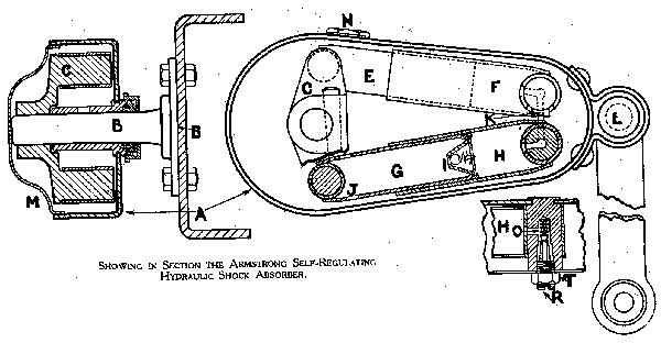
The flanged spindle B (to which is attached a double crank C) is fixed to the frame of the car.
On the crank pins are plungers E and G which work in their respective cylinders F and H.
These two cylinders are connected by a passage K so that oil is pumped from one to the other.
The cylinders, plungers and cranks are all inside the main casing A which is filled with oil and sealed by an oil-tight cover M. The casing or arm, since it acts as both, is connected at L to the axle of the car by suitable link.
As the axle moves to and from the car frame, so the plungers move in and out of their respective cylinders pumping oil from one to the other. The flow of oil, however, is governed by the valve gear placed in the passage K as follows:-
As the axle moves towards the frame the oil is pumped from the cylinder F to cylinder H, but as it has to pass the spring loaded ball valve O, a resistance governed by the tension on spring, is offered to the movement of the axle.
On the return or rebound stroke the oil is pumped from cylinder H to cylinder F, and as the ball valve only opens in one direction the oil must now find its way to cylinder F past the taper screw R which is adjustable to offer and desired resistance to the rebound of the car spring.
And oil leakage past the plungers is immediately replaced from the recuperating chamber through a hole in plunger G and into the cylinder H through the non-return valve I.
So now you know how it works…
